Introduction: Why Concrete Cracks
Concrete is strong in compression but inherently weak in tension. In reinforced concrete (RC) structures subjected to bending, shear, torsion, or axial tension, tensile stresses inevitably develop. Once these stresses exceed the concrete's tensile strength, cracks form. Reinforcement bars are embedded within the concrete to bridge these cracks and carry the tensile forces, ensuring the structure's integrity.
However, the mere presence of cracks, even if structurally managed by reinforcement, can impact the long-term performance and durability of the structure. Therefore, understanding and controlling the width of these cracks is a critical aspect of serviceability design.
This article primarily focuses on controlling flexural cracks, which are often the most critical for serviceability limit states in typical beams and slabs.
Crack Mechanisms and Their Importance
Reinforced concrete structures develop cracks through various mechanisms, each requiring specific control strategies:
- Flexural Cracking: Occurs in members subjected to bending moments, initiating on the tension face and propagating towards the neutral axis.
- Shrinkage Cracking: Results from volume reduction during concrete hardening, especially when restrained.
- Thermal Cracking: Caused by temperature gradients inducing differential expansion or contraction.
- Shear Cracking: Forms diagonally in regions of high shear stress.
Controlling crack widths serves several crucial purposes:
- Corrosion Protection: Narrower cracks limit aggressive agent ingress to reinforcement, preventing accelerated corrosion.
- Durability and Structural Integrity: Limiting crack widths maintains the concrete matrix's integrity and preserves effective member stiffness, ensuring proper deflection control.
- Aesthetics and Functionality: Visible cracks can be unacceptable in exposed structures, while watertightness is critical for liquid-retaining structures.
Theoretical Basis of Crack Width Calculation
The fundamental principle behind crack width calculation relates the strain in the reinforcement to the surrounding concrete. When concrete cracks, tensile force transfers to the reinforcement at the crack location, while between cracks, some tension returns to the concrete via bond.
The width of a crack (w) is essentially the integral of the strain difference between the steel and concrete over the crack spacing:
Where εsm is mean steel strain, εcm is mean concrete strain, and srm is mean crack spacing.
Mathematical Models
The crack width calculation involves these key relationships:
- Neutral axis calculation: For a cracked section, the neutral axis depth (x) can be determined from equilibrium conditions. Using a modular ratio approach (mr), the relationship can be expressed as:
k = √(2X + X2) - XThen the neutral axis depth x = k × d
where X = ρ × mr and ρ = As/(b×d) - Moment of inertia: For a cracked section, the moment of inertia is calculated as:
Icr = (b × x3)/3 + mr × As × (d - x)2
- Steel stress calculation: The stress in the reinforcement (fst) can be calculated as:
fst = mr × (M × (d - x) / Icr)where M is the applied bending moment
- Strain calculation: The strain at the level of the extreme tension fiber (e1) can be calculated as:
e1 = (fst / Es) × ((h - x) / (d - x))where Es is the modulus of elasticity of steel
- Final crack width: The crack width can be calculated using strain values and geometric parameters:
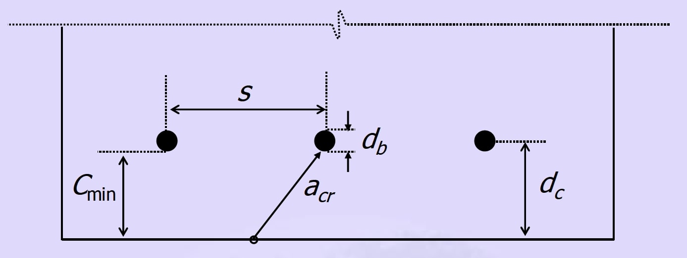
w = (3 × em × acr) / (1 + 2 × ((acr - c) / (h - x)))where:
- em is the mean strain
- acr is the distance from the point considered to the nearest longitudinal bar
- c is the cover to the reinforcement
- h is the overall depth of the member
Verification Criteria
According to IS 456:2000, the calculated crack width is typically compared to a permissible value of 0.3 mm for general exposure conditions. For more aggressive environments or water-retaining structures, stricter limits may apply.
Additionally, a stress limit of 0.55 × fy (where fy is the characteristic yield strength of reinforcement) is imposed to ensure that crack widths remain within acceptable limits.
Practical Crack Control Strategies
To effectively control crack widths in RC structures, designers can implement these key strategies:
- Limit Steel Stress: Keep service load reinforcement stress below 0.55fy, either by increasing steel area or member depth.
- Optimize Reinforcement Layout: Use more smaller-diameter bars at closer spacing rather than fewer larger bars for better crack distribution.
- Provide Adequate Cover: Balance durability requirements with crack control; excessive cover can lead to wider surface cracks.
- Control Concrete Properties: Manage mix design and curing to reduce shrinkage-related cracking.
Application in Different Elements
| Element | Key Considerations | Critical Distance Calculation |
|---|---|---|
| Beams | Concentrated reinforcement in layers; multiple bars per layer | acr = √((s/2)2 + dc2) - (db/2) |
| Slabs | Uniformly distributed reinforcement; calculated per unit width | acr = spacing / 2 |
Practical Application
While understanding the theory is vital, practical design involves applying code-specific formulas and limits. IS 456:2000 suggests a limiting crack width of 0.3 mm for general exposure conditions to protect against corrosion, with stricter limits for aggressive environments.
The theoretical steps for calculating crack width in a practical design scenario involve:
- Calculate the neutral axis depth based on section properties and reinforcement details
- Calculate the cracked moment of inertia
- Determine the steel stress under service load conditions
- Calculate strains and the resulting crack width
- Verify that the steel stress does not exceed the limiting value (0.55 × fy) and compare the calculated crack width with the permissible value
To apply these principles and perform calculations according to IS 456:2000, you can use our dedicated tool:
Ready to Calculate Crack Widths?
Use our advanced calculator to perform accurate crack width analysis according to IS 456:2000 standards.
Try Our Crack Width CalculatorConclusion
Crack width analysis requires both theoretical understanding and practical application. By balancing design variables like reinforcement layout, concrete properties, and member geometry, engineers can create durable structures that resist excessive cracking. Modern design codes provide empirical guidelines that, when applied with sound engineering judgment, ensure structures maintain serviceability throughout their design life.